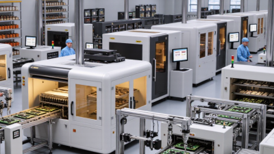
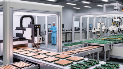
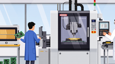
The 2026 circuit board equipment market is becoming more specialized, automated, and demanding. Global buyers must compare machines by production goals, board complexity, labor conditions, and after-sales support. A compact prototype line needs different tools from a high-volume automotive facility. The details matter.
This guide examines the top types of circuit board equipment available to international buyers. It covers PCB fabrication systems, laser drilling machines, exposure units, etching lines, solder paste printers, pick-and-place machines, reflow ovens, and automated optical inspection equipment. It also considers electrical testers, X-ray inspection systems, cleaning machines, and material-handling solutions. Each category serves a specific production stage. One weak stage can reduce the value of an entire line.
Practical purchasing experience shows that specifications alone rarely tell the full story. Buyers should check placement accuracy, feeder stability, thermal uniformity, software compatibility, energy use, and spare-parts availability. Supplier audits, sample production, factory acceptance tests, and service response records can reveal important differences. Certification and documentation must also match the destination market. Not always easy.
This overview uses an evidence-based approach, while recognizing that manufacturer claims require careful verification. A lower purchase price may hide expensive downtime, difficult maintenance, or limited training. Conversely, advanced automation may not suit every factory. That gap matters. The right decision balances performance, reliability, workforce skills, compliance needs, and long-term operating costs. Some recommendations may change as technologies improve, so buyers should review current data before signing contracts.
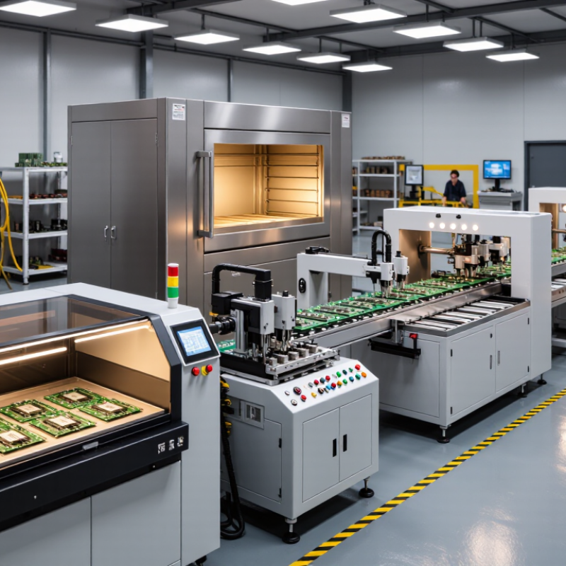
Circuit board equipment includes far more than assembly machines. It covers solder paste printers, pick-and-place systems, reflow ovens, inspection tools, testing stations, and material-handling equipment. Each stage affects the next one. A small printing error can become a weak solder joint after reflow.
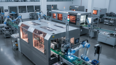
In 2026, global buyers are evaluating complete production systems rather than isolated machines. SPI checks paste volume and alignment before components are placed. AOI identifies missing parts, polarity errors, and visible solder defects. X-ray inspection helps examine hidden joints beneath packages. Functional testers then verify whether the finished board performs as designed.
The details matter.
Modern equipment also supports production data, recipe control, energy monitoring, and traceability. These features help factories compare batches and investigate defects faster. ESD-safe workstations, controlled storage, and reliable feeders remain essential, although they receive less attention in sales discussions. Experienced engineers often inspect maintenance access, calibration procedures, operator training, and spare-part availability before approving a purchase.
Automation can improve consistency, but it does not solve every process problem. A high-speed machine may create bottlenecks if inspection or material preparation is too slow. Integration is another concern. Equipment from different suppliers may exchange data poorly without careful planning. Buyers should test sample boards, review real yield records, and confirm service support in their operating region. Some decisions will still involve compromise. A lower-cost system may be practical for limited volumes, while demanding production may require stronger controls and better process visibility.
In 2026, global PCB buyers are evaluating equipment by manufacturing stage, not by machine name alone. This method clarifies process needs, production risks, and maintenance responsibilities. At the pre-production stage, engineers use CAM workstations, material preparation systems, and cutting equipment. These tools convert design data into controlled production files. A practical check includes file compatibility, panel size, laminate thickness, and trace-density requirements. Small mismatches here can become expensive defects later.
Imaging, drilling, and copper fabrication form the core circuit-building stages. Imaging equipment transfers patterns onto copper-clad panels, while mechanical or laser drills create vias and component holes. Plating systems then build reliable copper connections through those holes. Etching equipment removes unwanted copper, and solder-mask lines protect selected surfaces. Buyers should compare registration accuracy, chemical control, ventilation, water use, and output per shift. Datasheet numbers help, but factory-floor stability matters more.
Afterward, surface finishing, legend printing, assembly, and inspection equipment support delivery quality. Printing systems mark references, placement machines install components, and reflow systems control solder profiles. Automated optical inspection and electrical testers check open circuits, shorts, and missing parts. Practical sourcing reviews often show buyers overvalue speed and underestimate calibration time. That is a costly lesson. Equipment classification is useful, but it is not perfect. Some systems still need manual judgment during new-material trials. Specifications should include training, spare-part access, process records, and safety compliance.
PCB work depends on equipment that supports design, assembly, and testing as one connected process. Design teams commonly use PCB layout software, schematic capture tools, and signal integrity analyzers. These tools help engineers manage layer stacks, impedance, thermal paths, and component clearances. A reliable design review should include manufacturability checks before files reach the factory. Small spacing errors can become expensive production delays.
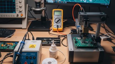
Assembly equipment turns digital files into physical boards. Stencil printers apply solder paste across fine-pitch pads with controlled pressure. Pick-and-place machines position components at high speed and repeatable accuracy. Reflow ovens then create a stable solder profile across multiple temperature zones. For prototypes, benchtop placement systems and compact reflow units may offer better flexibility. Production teams should verify feeder compatibility, changeover time, and maintenance access. Speed alone is not enough.
Testing equipment protects reliability after assembly. Automated optical inspection detects missing parts, solder bridges, and placement shifts. Flying-probe testers check electrical connections without requiring a dedicated fixture. In-circuit testers provide deeper coverage when production volumes justify their setup cost. Functional testers simulate real operating conditions, such as power delivery or communication signals. X-ray inspection can reveal hidden solder joints beneath advanced packages. No production line is perfect. Operators still need training, calibration records, and clear response procedures. I have seen teams overvalue automation and underestimate inspection programming. That assumption can fail when a new board design changes pad geometry or thermal behavior.
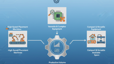
In 2026, circuit board equipment selection will depend less on catalog size than on production reality. High-mix factories need flexible SMT placement, quick-change tooling, AOI, and traceable testing. High-volume lines prioritize cycle time, feeder capacity, stable reflow, and automated material handling. Operators still matter. Their practical feedback often reveals defects that dashboards miss.
The International Federation of Robotics reported 541,302 industrial robots were installed worldwide in 2023. This trend supports investment in robotic loading, inspection, and warehouse transfer systems. However, automation is not automatically efficient. Poor programming can move defects faster. Equipment should connect with MES platforms, barcode systems, and real-time quality records. IPC standards, including IPC-A-610, also help buyers define acceptance requirements before installation.
SEMI’s Year-End 2024 Forecast projected global semiconductor manufacturing equipment spending at 112.8 billion dollars in 2025. Although this figure covers semiconductor production, it signals stronger automation pressure across the electronics supply chain. Buyers should compare total operating cost, not only purchase price. Energy consumption, maintenance access, spare-part availability, and training can change the calculation quickly. A slower machine may perform better when changeovers are frequent. I have seen selection teams overvalue advertised speed. That is a useful mistake to examine before approving a 2026 production line.
| Equipment Type | Primary Production Function | Typical Automation Level | Representative Capacity or Accuracy | Typical Board or Process Compatibility | Main Selection Drivers | Common Buyer Profile | 2026 Investment Priority |
|---|---|---|---|---|---|---|---|
| Solder Paste Printer | Applies solder paste to PCB pads through a stencil before component placement. | Automatic loading, stencil alignment, paste inspection, cleaning, and recipe changeover options. | Typical print-position repeatability: approximately ±25–50 µm, depending on machine configuration and process conditions. | SMT boards, fine-pitch components, lead-free solder processes, and mixed-volume production. | Print repeatability, automatic alignment, stencil support, changeover time, paste control, and operator-error reduction. | Contract manufacturers, automotive electronics producers, industrial-control manufacturers, and high-mix SMT plants. | High |
| SPI System | Measures solder-paste volume, height, area, offset, and bridging immediately after printing. | Inline inspection with automatic defect classification, statistical process control, and feedback to the printer. | 3D measurement resolution and accuracy vary by system; process control commonly focuses on paste-volume consistency rather than visual presence alone. | Fine-pitch SMT, miniaturized assemblies, high-reliability products, and low-defect production lines. | False-call rate, measurement repeatability, inspection speed, closed-loop process control, and data integration. | High-volume or high-reliability manufacturers seeking early defect detection. | High |
| Pick-and-Place Machine | Places surface-mount components onto solder-paste-coated PCB positions. | High-speed automated placement with feeders, tray handling, vision alignment, and software-based line balancing. | Production speed is commonly specified in components per hour; practical output depends on component mix, board complexity, and changeover requirements. | From small passive components to integrated circuits, connectors, and irregular parts, subject to feeder and placement-head capability. | Placement speed, accuracy, feeder cost, component range, changeover time, software connectivity, and serviceability. | All automated SMT producers; machine configuration is usually matched to volume and product mix. | High |
| Reflow Soldering Oven | Melts solder paste under a controlled thermal profile to form solder joints. | Automated conveyor transport, recipe control, profile monitoring, nitrogen options, and remote production data access. | Typically uses multiple independently controlled heating and cooling zones; thermal uniformity and profile repeatability are key performance indicators. | Most lead-free and tin-lead SMT assemblies, including multilayer boards and thermally diverse component populations. | Zone configuration, conveyor width, energy use, cooling control, nitrogen consumption, thermal uniformity, and maintenance access. | SMT lines requiring stable solder quality and repeatable thermal processing. | High |
| AOI System | Uses cameras and software to inspect component presence, polarity, placement, soldering, and visible assembly defects. | Inline or offline operation with automatic program generation, defect classification, and traceability integration. | Inspection coverage and detection capability depend on camera resolution, viewing angle, lighting, board complexity, and algorithm quality. | SMT and mixed-technology assemblies where visible defects can be assessed optically. | Coverage, false-call control, programming effort, 2D/3D capability, inspection speed, and traceability. | Manufacturers balancing quality assurance with labor reduction and process traceability. | High |
| X-Ray Inspection System | Examines hidden solder joints and internal structures that cannot be verified by ordinary optical inspection. | Automated image acquisition, programmable inspection routines, defect analysis, and digital reporting. | Commonly used for voiding, head-in-pillow defects, hidden joints, vias, and internal package features; capability depends on resolution and inspection geometry. | Ball-grid arrays, bottom-terminated components, power modules, multilayer boards, and dense assemblies. | Image resolution, inspection area, throughput, radiation safety, automation, and analysis software. | Automotive, aerospace, medical, power-electronics, and other high-reliability producers. | Selective |
| Wave Soldering Machine | Solders through-hole and selected bottom-side components by passing boards over a molten solder wave. | Automated conveyor, flux application, preheating, solder temperature control, and recipe management. | Best suited to repeatable through-hole production; actual capacity depends on conveyor width, board spacing, solder pot design, and product geometry. | Through-hole assemblies, larger components, and boards designed for bottom-side wave exposure. | Flux control, solder consumption, thermal profile, conveyor flexibility, maintenance, and nitrogen use. | High-volume through-hole or mixed-technology production lines. | Medium |
| Selective Soldering Machine | Applies solder to specific through-hole joints without exposing the entire assembly to a solder wave. | Programmable nozzle movement, localized fluxing, preheating, solder-height control, and automatic recipe execution. | Process capability is defined by nozzle access, solder-joint geometry, thermal control, and programmed movement accuracy. | Mixed-technology boards, densely populated assemblies, heat-sensitive components, and products with restricted solder access. | Programming flexibility, nozzle range, thermal management, changeover time, solder control, and board support. | High-mix manufacturers replacing manual soldering or reducing wave-solder masking requirements. | High |
| PCB Cleaning System | Removes flux residues, ionic contamination, particles, and process chemicals from assembled boards. | Automated spray, immersion, or batch cleaning with filtration, temperature control, drying, and fluid monitoring. | Cleaning effectiveness depends on chemistry, pressure, temperature, time, board geometry, and residue type; ionic cleanliness is commonly verified separately. | High-reliability electronics, no-clean process exceptions, conformal-coating preparation, and assemblies sensitive to contamination. | Cleaning chemistry, water consumption, drying performance, waste treatment, compatibility with components, and process validation. | Medical, automotive, aerospace, power, and industrial electronics manufacturers. | Selective |
| Depaneling System | Separates individual PCBs from production panels after assembly while controlling mechanical stress. | Programmable routing, laser cutting, blade cutting, vision alignment, dust extraction, and automated loading options. | Cutting accuracy and stress levels depend on panel design, tool type, material, thickness, and support method. | Rigid FR-4 panels, aluminum-backed boards, flexible or rigid-flex assemblies, depending on the cutting technology. | Panel format, edge quality, board stress, dust control, tooling cost, cycle time, and design flexibility. | High-mix assemblers and producers of compact or mechanically sensitive electronic products. | Medium |
| In-Circuit Test System | Checks component values, opens, shorts, orientation, and selected electrical connections using test access points. | Automated fixture-based testing with software-controlled test sequences and production data logging. | Test coverage depends heavily on fixture access, board design-for-test, component technology, and test-program quality. | Stable products with dedicated fixtures, repeatable designs, and sufficient electrical test access. | Coverage, fixture cost, programming time, test speed, maintenance, and product-change frequency. | Medium- to high-volume producers with mature product designs. | Medium |
| Functional Test System | Verifies whether the completed board or electronic assembly performs its intended electrical and operational functions. | Automated test sequencing, programmable instruments, barcode traceability, and connection to manufacturing databases. | Test scope is product-specific and may include power, communication, sensing, timing, firmware, and load-response checks. | Finished control boards, power supplies, communication modules, automotive electronics, and embedded systems. | Test coverage, fixture design, software flexibility, data traceability, cycle time, and integration with final assembly. | Manufacturers requiring end-of-line validation beyond visual or structural inspection. | High |
| Laser Marking System | Marks serial numbers, date codes, 2D identifiers, logos, or process information on PCBs and assemblies. | Automated vision positioning, barcode verification, recipe management, and manufacturing-execution-system connectivity. | Mark quality depends on laser type, wavelength, surface finish, contrast, marking speed, and material compatibility. | Traceability-focused production, regulated products, serialized assemblies, and products requiring permanent identification. | Mark permanence, readability, data integration, cycle time, material compatibility, safety enclosure, and verification. | Global manufacturers needing product genealogy and automated traceability. | Selective |

Planning note: Capacity, accuracy, energy use, and inspection performance are representative industry ranges or selection criteria rather than guaranteed specifications. Final equipment selection should be validated against board dimensions, component mix, production volume, factory utilities, regional safety requirements, and process qualification results.
In 2026, buyers will compare drilling systems, printers, placement machines, reflow ovens, inspection tools, and testers. Yet equipment lists rarely reveal supplier quality. A reliable supplier should explain where each machine fits your board materials, production volume, and tolerance requirements. Ask for documented specifications, operating ranges, calibration procedures, and maintenance intervals. Request recent test data, not only catalog claims. Small details matter. Check installation space, power stability, ventilation, software language, and replacement-part availability. Ask for evidence.
Experienced purchasing teams should audit factory controls, technician training, quality records, and shipment inspection methods. Video calls help, but an independent inspection provides stronger evidence. Request sample boards using comparable copper thickness, layer count, and surface finish. Measure defect rates at normal production speed. A polished demonstration can hide difficult conditions. A common mistake is focusing on machine price, then discovering costly training, delayed parts, or incompatible data formats. That choice looked efficient on paper. It was not. Supplier references should include comparable overseas installations, response times, warranty boundaries, and escalation contacts. Confirm documents for electrical safety, electromagnetic compatibility, and local import requirements. Do not accept copied certificates without checking issuing bodies and validity dates. Require acceptance criteria in writing, including accuracy, throughput, downtime limits, and remedies when results fall short.