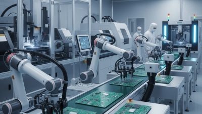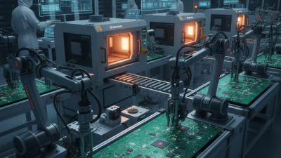
Choosing electronic assembly equipment is not simply a matter of comparing prices, speeds, or impressive specifications. It is a process decision. The right machine must fit your products, operators, floor space, quality targets, and future production plans. A compact PCB prototype line needs different tools from a high-volume automotive facility.
Ronald C. Lasky, a recognized SMT and electronics manufacturing specialist, offers a practical warning: “The best equipment is not always the most expensive equipment; it is the equipment that best fits the process.” That principle deserves attention. A fast pick-and-place machine may look attractive, yet it can become a poor investment if your feeder setup is limited. A reflow oven may provide excellent thermal control, but it still needs suitable ventilation, maintenance access, and operator training.
Begin with your actual assembly requirements. Consider board size, component range, placement accuracy, throughput, soldering method, inspection needs, and expected product changes. Look closely at daily details. Can an operator load feeders without strain? Can technicians access the oven after a temperature alarm? Does the software create useful production records, or only display complicated screens?
Small details matter.
Experience also teaches humility. Forecasts can be wrong. Product designs can change quickly. Therefore, leave room for adjustments instead of buying only for today’s output. Speak with equipment suppliers, experienced operators, and independent manufacturing specialists. Request demonstrations using your own boards when possible.
This guide explains how to evaluate electronic assembly equipment with evidence, practical judgment, and realistic limitations. No machine removes every production risk. Better choices simply make those risks easier to control.
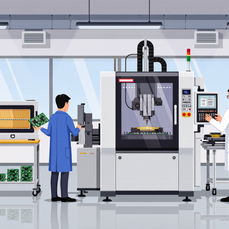
Choosing Electronic Assembly Equipment for Your Needs
Choosing electronic assembly equipment starts with a precise production definition. Record board dimensions, layer count, component package types, and placement density. Note whether your products use fine-pitch parts, through-hole components, or both. A small prototype line may need flexible placement and inspection tools. A high-volume line demands stable cycle times, feeder capacity, and repeatable process control. Measure actual demand, not optimistic forecasts. Monthly units, shift length, and expected product changes should guide capacity planning.
Set measurable production goals before comparing equipment. Define acceptable first-pass yield, placement accuracy, changeover time, and rework limits. Include traceability requirements for batches, operators, and process settings. Quality data should be collected at each critical stage, including solder paste inspection and final functional testing. Safety, ventilation, electrical protection, and operator ergonomics also belong in the specification. These details are easy to overlook. They often create expensive delays later.
A practical assessment includes samples, trial runs, and discussions with experienced technicians. Ask whether the equipment can handle your smallest package and most demanding board. Check service access, training needs, spare parts, software compatibility, and calibration procedures. Do not size a system only for today’s product. Leave measured room for reasonable growth, but avoid paying for unused speed. Our first capacity estimate was wrong because changeover time was ignored. That mistake showed why real production trials matter more than brochure figures. Document assumptions, test results, and unresolved concerns before approving the purchase.
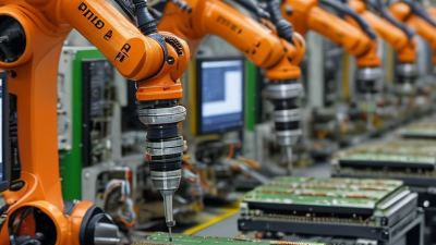
Choosing electronic assembly equipment starts with comparing process requirements, not browsing machine features. A stencil printer suits solder paste deposition, while a pick-and-place machine handles component placement. Reflow ovens then control soldering through measured thermal profiles. These machines support high-volume surface-mount production, but they may be excessive for prototypes or frequent product changes.
For mixed production, flexible placement equipment and quick-change feeders can reduce setup delays. Manual benches remain practical for small batches, repairs, and unusual components. Selective soldering fits through-hole joints that need controlled heat, while wave soldering favors larger, repeatable volumes. Automatic optical inspection checks visible defects, whereas X-ray inspection reveals hidden joints beneath packages. The right inspection level depends on product risk, package density, and customer requirements.
Deloitte’s 2024 Smart Manufacturing and Operations Survey reported that 86% of manufacturers expect smart manufacturing to become important for competitiveness within three years. That supports investment in connected equipment, but connectivity alone cannot fix poor process control. IPC quality guidance also emphasizes process capability, traceability, and documented inspection criteria. In practice, a production line should match its weakest process. A fast placer cannot compensate for unstable paste printing. I have seen equipment comparisons focus too heavily on placement speed. That is an imperfect approach. Changeover time, feeder accuracy, thermal profiling, operator training, maintenance access, and data compatibility often decide the real return. A careful trial run using representative boards can expose problems that brochures hide.
How to Choose Electronic Assembly Equipment for Your Needs?
Evaluate Capacity, Precision, Compatibility, and Automation
Choosing electronic assembly equipment starts with the workload, not the advertised speed. Estimate daily boards, component ranges, changeover time, and peak demand. Leave room for growth, but avoid paying for idle capacity. Measure twice. An experienced production engineer will also check feeder loading, material flow, and operator access.
Precision must match the smallest pitch, placement tolerance, inspection requirement, and rework risk. Ask for repeatability data, calibration intervals, and sample results using your actual components. A machine may perform well in a demonstration, yet struggle with warped boards or moisture-sensitive parts. Real samples matter. Document acceptance limits before testing.
Compatibility covers more than board dimensions. Confirm software formats, feeder types, tooling, power requirements, and communication with existing equipment. Review maintenance records, training needs, and spare-part availability before signing an agreement. I once focused on throughput and overlooked fixture changes; the resulting delays were expensive. Automation should remove repetitive errors, not create a system nobody can maintain. Compare manual, semi-automatic, and fully automated steps against staffing and quality controls. Useful features include recipe management, traceability, alarm history, and controlled access. Ask operators to test the interface. Their feedback may challenge your assumptions.
| Equipment Type | Primary Function | Typical Capacity | Typical Precision | Compatibility Considerations | Automation Level | Best Fit | Key Evaluation Point |
|---|---|---|---|---|---|---|---|
| Stencil Printer | Applies solder paste to printed circuit board pads through a stencil. | Approximately 10–30 boards per hour for manual or semi-automatic units; higher for inline systems. | Paste-placement accuracy commonly ranges from about ±0.05 to ±0.10 mm, depending on equipment configuration. | Check board dimensions, stencil frame size, board thickness, fiducial recognition, and paste-handling requirements. | Semi-automatic to High | Prototype, laboratory, and medium-volume SMT production. | Prioritize repeatable paste deposition, alignment stability, cleaning method, and changeover time. |
| Pick-and-Place Machine | Places surface-mount components onto solder-pasted circuit boards. | Entry-level systems: roughly 1,000–8,000 components per hour; advanced systems may exceed 20,000 components per hour. | Typical placement accuracy is approximately ±0.05 to ±0.10 mm; fine-pitch performance depends on vision and feeder quality. | Confirm support for component packages, feeder types, board size, component height, and available CAD or centroid-file formats. | High | Repeated PCB assemblies with moderate to high component counts. | Compare effective throughput rather than headline speed, including feeder loading, nozzle changes, and setup time. |
| Reflow Oven | Melts solder paste under a controlled thermal profile to form solder joints. | Batch systems handle one or several boards per cycle; conveyor systems commonly support continuous production. | Temperature control is commonly within approximately ±1–3°C in stable zones; actual solder-joint quality depends on profiling. | Evaluate board size, conveyor width, number of heating zones, nitrogen requirements, and maximum component temperature limits. | High | SMT production requiring consistent soldering results. | Look for sufficient thermal zones, profile storage, energy efficiency, exhaust control, and easy maintenance access. |
| Wave or Selective Soldering System | Solders through-hole components using a molten solder wave or a programmable solder nozzle. | Wave systems are suitable for continuous medium-to-high volume; selective systems process targeted joints on mixed-technology boards. | Selective soldering positioning is commonly around ±0.10–0.25 mm, depending on nozzle and board-support design. | Check through-hole layout, board underside clearance, solder alloy, flux type, pallet design, and thermal sensitivity. | Medium to High | Mixed-technology assemblies and boards with significant through-hole content. | Select wave soldering for volume and selective soldering for flexible, localized, or thermally sensitive assemblies. |
| Automated Optical Inspection System | Inspects solder paste, component presence, polarity, placement, and visible solder defects. | Inline systems can inspect boards continuously at production-line speed; offline systems are suited to lower volumes. | Inspection capability depends on camera resolution, lighting, optics, and algorithm settings; it is not the same as placement accuracy. | Verify support for board dimensions, component libraries, barcode formats, 2D inspection, and programming data import. | High | Processes requiring fast, repeatable visual inspection and traceable defect data. | Assess false-call rate, defect coverage, programming effort, review workflow, and data export options. |
| X-Ray Inspection System | Examines hidden solder joints, voids, thermal pads, and internal structures that cannot be seen optically. | Usually operates as an offline or semi-automated inspection step; throughput varies with image resolution and inspection area. | Resolution commonly ranges from tens of micrometres to over 100 micrometres, depending on system design and magnification. | Consider board size, component density, image contrast, safety requirements, and whether 2D or computed-tomography capability is needed. | Basic to High | Dense assemblies, bottom-terminated components, power modules, and critical solder joints. | Use when hidden defects materially affect reliability; balance inspection depth against cycle time and operating cost. |
| In-Circuit Test System | Checks component values, electrical connections, shorts, opens, and selected circuit characteristics using a test fixture. | Test time may range from a few seconds to several minutes per board, depending on coverage and fixture design. | Measurement accuracy depends on the instrument range, test method, fixture, and calibration interval. | Confirm test-point access, fixture compatibility, board revision control, software support, and programming interfaces. | Medium | Stable, repeatable products manufactured in medium or high volumes. | Evaluate test coverage, fixture cost, product-change flexibility, fault isolation, and maintenance requirements. |
| Functional Test Station | Verifies whether the completed product performs its intended electrical or electronic functions. | Capacity is product-specific; automated stations can test multiple units sequentially or in parallel. | Accuracy depends on measurement instruments, test software, fixtures, sensors, and reference standards. | Review interface requirements, power levels, communication protocols, safety interlocks, and product-specific fixtures. | Manual to High | Finished products where operational performance is more important than component-level testing alone. | Define measurable acceptance criteria and ensure the station can record serial numbers, results, and failure codes. |
| Cable and Wire Processing Equipment | Cuts, strips, crimps, labels, and tests wires or cable assemblies. | Manual tools suit low volume; automated machines can process hundreds or more wire ends per hour, depending on operations. | Cut and strip repeatability is commonly in the sub-millimetre range; crimp quality requires validated tooling and force control. | Check wire gauges, insulation materials, terminal families, applicator tooling, crimp standards, and conductor diameter range. | Manual to High | Harness production and assemblies with repetitive wire-processing operations. | Focus on crimp consistency, tool changeover, material traceability, operator ergonomics, and pull-test capability. |
| Depaneling Machine | Separates individual circuit boards from a manufacturing panel after assembly. | Capacity depends on panel layout and cutting method; routing, laser, and blade systems support different production needs. | Cut accuracy is commonly within approximately ±0.10–0.30 mm, depending on tooling and board design. | Assess panel thickness, routing paths, edge clearance, component height, dust control, and stress limits. | Semi-automatic to High | Panelized PCB production where manual breaking could damage boards or components. | Choose the cutting method according to allowable board stress, edge quality, throughput, and dust-management requirements. |
| The specifications shown are representative industry ranges rather than guaranteed equipment ratings. Actual capacity and precision depend on product design, material handling, programming, process settings, operator skill, maintenance, and environmental conditions. Always validate requirements with sample boards and documented process trials. | |||||||
Choosing electronic assembly equipment requires more than comparing purchase prices. Build a five-year cost model before approving any quotation. Include tooling, electricity, calibration, consumables, software updates, spare parts, and downtime. Ask for service response times and preventive maintenance schedules. A low quote can become expensive. Use real production data, not optimistic estimates.
Maintenance should match your team’s actual skills. Inspect access panels, cleaning points, and replacement procedures before installation. Record how many minutes routine maintenance requires. If technicians need special tools or outside support, include those costs. Safety deserves a line-by-line review. Check guarding, emergency stops, hot surfaces, moving mechanisms, fumes, and noise. Confirm ESD controls and ventilation suit the materials. Document lockout procedures and routine inspections according to local requirements.
Operator training affects quality and injury risk. Require hands-on practice with setup, changeovers, alarms, and emergency procedures. Use short visual instructions near the work area. Training time is a real cost. Measure setup errors, rejects, and near misses after launch. If results decline, pause and retrain instead of blaming operators. A spreadsheet may still mislead. Conditions change. Recheck costs after three months, and leave room for mistakes in the original plan.
Five-year total cost planning model: assess purchase cost, maintenance, safety, and operator training before selecting equipment.
The model allocates a normalized five-year equipment budget across common ownership categories. Initial purchase cost is only one part of the decision; maintenance, operator training, safety controls, consumables, and downtime should also be included when comparing equipment options.
Choosing electronic assembly equipment should begin with the next product mix, not this quarter’s purchase price. The International Federation of Robotics’ World Robotics 2024 report recorded 541,302 industrial robot installations worldwide in 2023, a 10% annual increase. That growth signals a practical direction: equipment must accept automation without forcing complete line replacement. Check feeder capacity, board-size range, changeover time, software interfaces, and inspection compatibility. Small details matter. A fast machine with fragile software can become tomorrow’s bottleneck.
Future readiness also means planning for skills, data, and compliance. SEMI’s World Fab Forecast projected semiconductor manufacturing equipment spending at about 122 billion dollars in 2025. This investment reflects continuing pressure for capacity and process control across the electronics supply chain. Select platforms that record traceability data, support remote diagnostics, and connect with manufacturing execution systems. However, do not automate every step blindly. A manual verification point may prevent costly escapes when product volumes remain uncertain.
Ask suppliers for realistic demonstrations using your boards, components, solder profiles, and changeover schedule. Measure first-pass yield, placement accuracy, downtime recovery, and operator training hours. Leave electrical, floor-space, and utility margins for expansion. Many plans assume perfect uptime; factories rarely behave so neatly. A better decision includes a written upgrade path, spare-part availability, and compatible tooling for future designs. Review the plan with production, quality, maintenance, and finance teams before signing.